Cat5e Ethernet Cables
18-10-2018
This document was written in an effort to provide basic background information regarding the 568A and 568B wiring standards. It will also define the differences between these standards. In addition, steps on how to create standard and crossover cables are provided.
Both the 568A and 568B are the two-color code schemes used to correctly wire the RJ45 eight-position modular plugs. These two color codes are approved by the American National Standard Institute/Telephone Industry Association/Electronics Industry Association (ANSI/TIA/EIA) wiring standards. There is no difference, whatsoever, between the two wiring schemes in connectivity or performance when connected from one device to another as long as the devices are wired for the same scheme. The only time when one scheme has an advantage over the
Cables are generally made up of 8 wires twisted together in 4 pairs. Each pair is easily identified by one of four primary colors and is intended to carry a signal and its return. The 568A wiring pattern is recognized as the preferred wiring scheme for
However, N-TRON adopted the 568B standard since it is the most widely used in the industry today. It matches the older AT&T 258A color code. It is also approved by the ANSI/TIA/EIA Standard. This scheme also provides one pair for backward compatibility to the USOC wiring scheme.
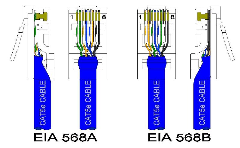
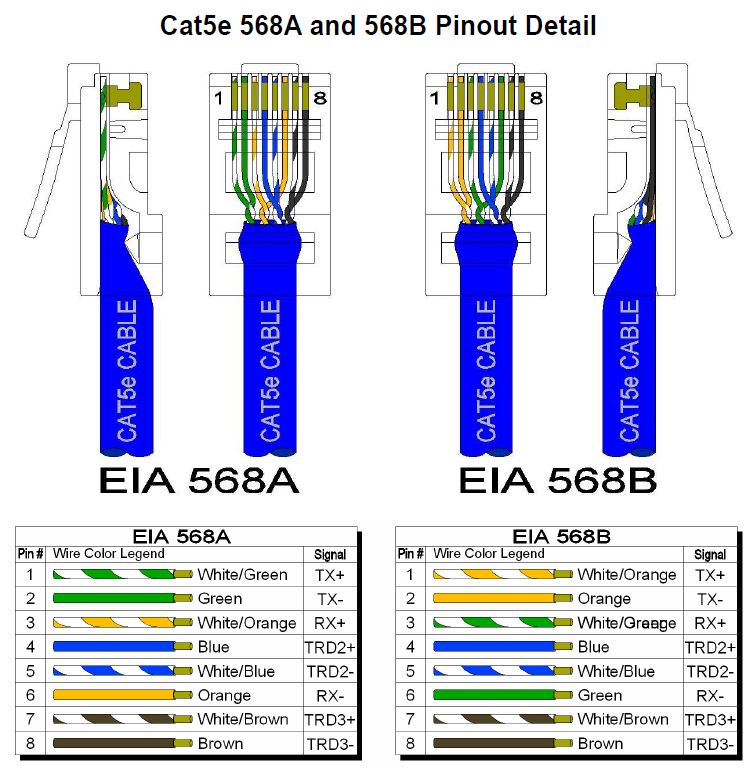
The below illustration will assist you in identifying the differences between the 568A and 568B color schemes. The main difference between the two schemes is that the orange and green pairs are interchanged. These standards specify a maximum segment length of 100 meters (328 feet) between two devices. This length includes patch panels and cables. When longer distances are desired, the use of switches, repeaters or fiber optic media may be required.

A cable can be wired with correct continuity, but not with
If the only error is a split pair error, the cable has correct continuity and will likely cause crosstalk. Crosstalk is the bleeding of signals carried by one pair of conductors onto another pair through the electrical process of induction. The conductors do not need to make contact with each other as the crosstalk is transferred magnetically.
This is an unwanted effect that can cause slow transfer or completely inhibit the transfer of data signals over a long cable segment. The purpose of the wire twists found in
Similarly, Electro Magnetic Interference (EMI) is an unwanted signal that is induced into the cable. The difference is that EMI is typically induced from a source that is external to the cable. This could be an electrical power cable or
Attenuation is the loss of signal in a cable segment due to the resistance of the wire plus other electrical factors that cause additional resistance. Longer cable length, poor connections, bad insulation, high levels of crosstalk and EMI will all increase the total level of attenuation.
The 568A and 568B standards were developed to provide more effective communications for longer distances in a Cat5e cable segment than using
Creating Cat5e Standard and Crossover Cables
Before you begin creating standard Cat5e patch cables, it is important to point out that the method outlined here is only one method. It is by no means the best method. Also, make sure you have all the necessary tools and materials before you begin. You will need a length of Cat5e certified cable and several RJ-45 connectors. For best results, we recommend using a quality ratcheting tool such as the popular IDEAL Telemaster™ Tool for cutting and terminating RJ-45 plugs.
- Most crimp tools have two blades: one designed to cut through a cable completely and the other designed to help remove the cable’s outer jacket. Use the first blade to cut the cable to length. Then, use the second blade to strip the cable’s outer jacket to remove about one inch, so that all the wires inside are exposed. Be careful not to cut the inside wires when stripping the cable’s jacket insulation.
- With the jacket removed, you will find eight wires within the Cat5e cable. If a string is present, cut the string off, and untwist the wires back to within
one-eighth inch of the jacket. - Fan the wires out from left to right in the order they are to be crimped. Using the same color scheme (568A or 568B) at both ends will create a standard patch cable as shown in the 568A-568A and 568B-568B illustrations below.
- With the wires aligned and flattened out, use the cutting blade to evenly trim the wires while leaving approximately one-half inch exposed.
- With the clip facing away from you, carefully insert the wires into the RJ45 connector as shown below.
- Once two RJ45 connectors have been installed at both ends, you will need to determine the quality of all connections to ensure the pinouts have been terminated properly. This is a very important step that is often overlooked mostly due to the expense of the testing equipment. The LanRover Pro TP600 will assist you in identifying shorts, opens,
miswires , reversals, and split pairs. In addition, this professional tester will help determine the final length of the cable you made.

Two Ethernet switches may be connected together with a standard patch cable as long as both devices are compliant with the MDIX standard. N-TRON Ethernet switches use this technology on all 10/100 RJ45 ports. Basically, the MDIX standard automatically performs the crossover functions without user configuration. It allows the switch to properly align the conductors internally.
In some situations,

Shielded Cat5e Cable Detail
The use of shielded cables between devices is not required for most N-TRON devices (please consult the user manuals for specific details). If the use of shielded cables is required, it is generally recommended to only connect the shield at one end to prevent ground loops and interfere with

In the event all Cat5e patch cable distances are small (i.e. All Ethernet devices are located the same local cabinet and/or
Cat5e 568A and 568B Pinout Detail

CREDIT The information in this white paper was first published by N-TRON. In an effort to bring out customers the best possible information, B+B SmartWorx (formerly B&B Electronics) has received permission to republish this document. B+B SmartWorx thanks N-TRON for allowing us to distribute this information to our customers. You can visit their site at https://www.n-tron.com.
