The Fine Art of Analog Signal Sampling
10/23/2018
Reducing Quantization Error and Aliasing Inaccuracy in Analog/Digital Conversion
The fine art of converting a continuous analog signal into synthesized discrete digital information (a mouthful for A/D conversion) involves two important accuracy considerations. It also reflects the characteristics of the sampled analog signal.
These two considerations involve:
1. breaking down the analog signal’s magnitude into discrete levels or steps (quantization)
2. setting the data sampling rate based on the signal’s maximum change frequency component (aliasing and the Nyquist Frequency)
Quantization Error
The amount of inaccuracy between the analog magnitude and the converted discrete digital value is known as “quantization error”. (See Figure1 and Figure 2.) The number of discrete digital values available to represent the continuous analog signal is set by the number of bits contained in the digital converter. The higher the bit level of the converter and the finer the resolution of the digital values, the more accurate the digital representation of the analog signal will be.
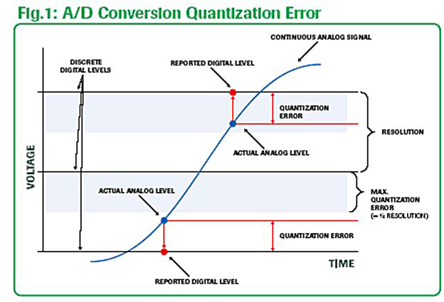
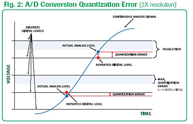
Defining the acceptable resolution of your A/D conversion sets the required bit-level for your digital converter.
As an example, for a 0 to 50V analog signal using an 8-bit A/D converter, the voltage range will be divided into 256 discrete levels. Each digital level will be equally spaced by 0.195V (50V / 256 levels) starting from 0.0 (i.e. 0.000V = Digital 0, 0.195V = Digital 1, 0.390 = Digital 2, . . . 50.00V = Digital 255). Quantization error is 1/2 of the converter’s resolution.
In this example, you need to decide if the resolution of 0.195V and quantization error of 0.098V provided by an 8-bit converter is acceptable. Or, do you need the 0.0122V resolution and 0.0061v quantization error of a 12-bit converter? Or, even the resolution of 0.00076V and 0.00038V quantization error of a 16-bit converter?
Aliasing Inaccuracy (sampling at too slow of a rate)
Analog signals contain frequency components that make up the characteristics of the signal’s waveform. If we sample the signal at too low of a rate, the finer detail of the signal may be missed as it is converted to a digital equivalent. Slow sampling tends to miss the
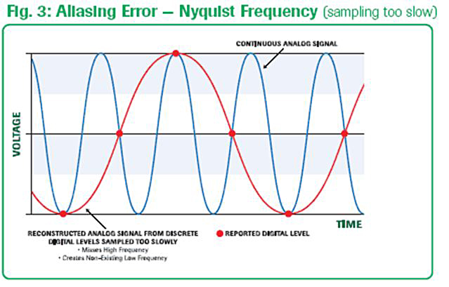
The Nyquist Theorem states that the sampling rate must be at least twice the highest frequency component contained within the analog signal.
So, for example, with a signal that contains 10Hz, 500Hz, and 5KHz components, the minimum sampling rate is 2 x 5KHz or 10KHz = 10,000 samples/sec. If the sampling rate of the A/D converter is capable of it, it is even better to sample at 4x to 8x the highest frequency. This will ensure resolving the signal’s true waveform.
Two Decisions
The fine art of Analog/Digital conversion all comes down to two basic decisions:
1. What
2. The minimum sampling rate to truly capture the essence of the analog signal is to know the highest frequency component and sample at a minimum rate of at least twice the highest frequency.
With these two factors under control, you are ready to go.